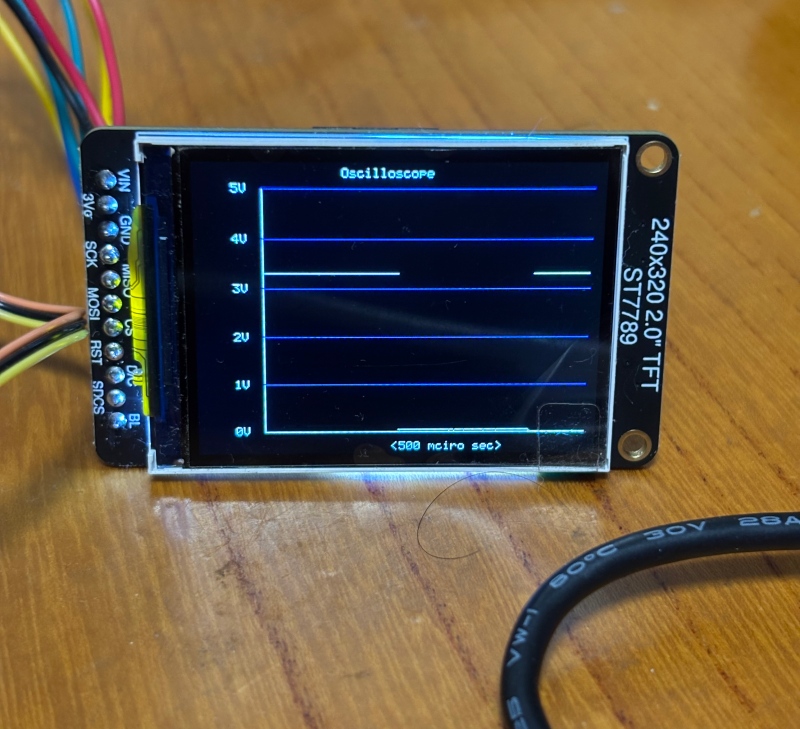
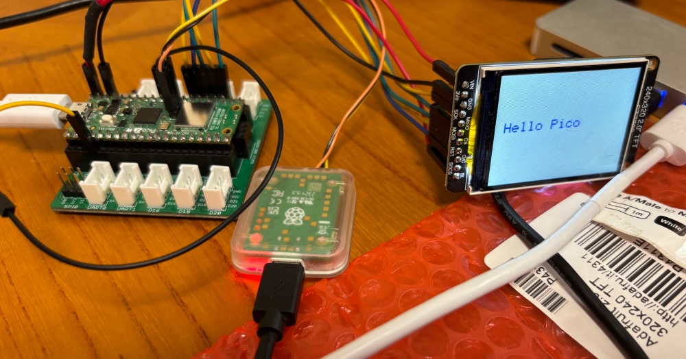
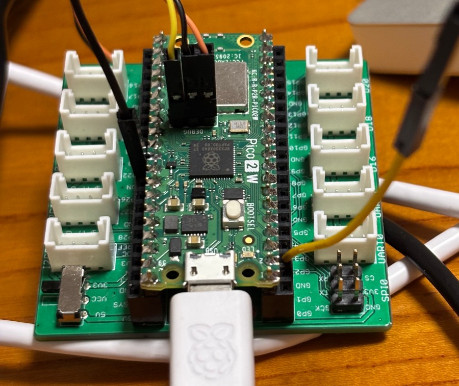
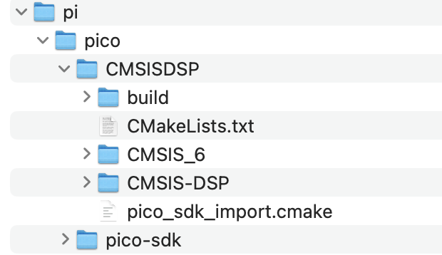
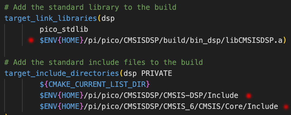
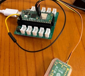
pico-sdkとCMSIS-DSPを使って作る、ラズピコ2で動かすスペアナプロジェクトの基本ロジックを作ってみた
・ADCはDMA転送を使う、割り込み処理の中でFFT
大雑把にはそうだけども、実はラズピコのADCをDMAモードで動かすとクロックデバイドが効かない、つまり常におよそ500KHzサンプルモードになってしまう、対応方法は500KHzでサンプル(256*10個)した後にIIRの一次フィルタ処理、その後に10個ごとのデータを使えば50KHzサンプル相当になる
・窓はHanning窓を使う
おそらく一般的だろうし、
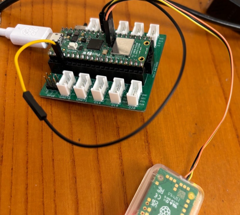
・テスト用の信号はPWM機能を使う
picoの特徴としてsm(state machine)とPWM機能、どちらもCPUの介在なしで信号発生ができる、があるからPWM使って方形波を作成してADCへの入力とする
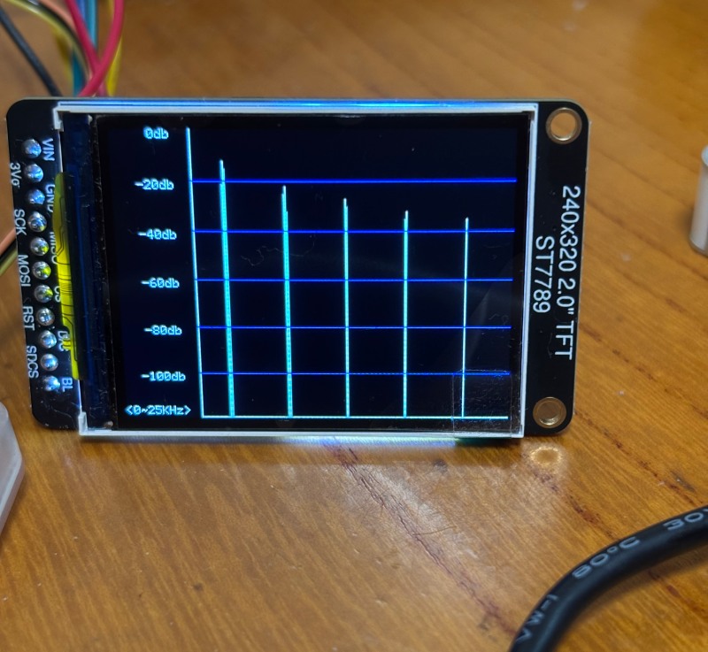
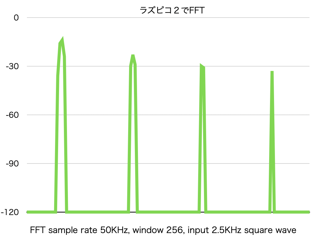
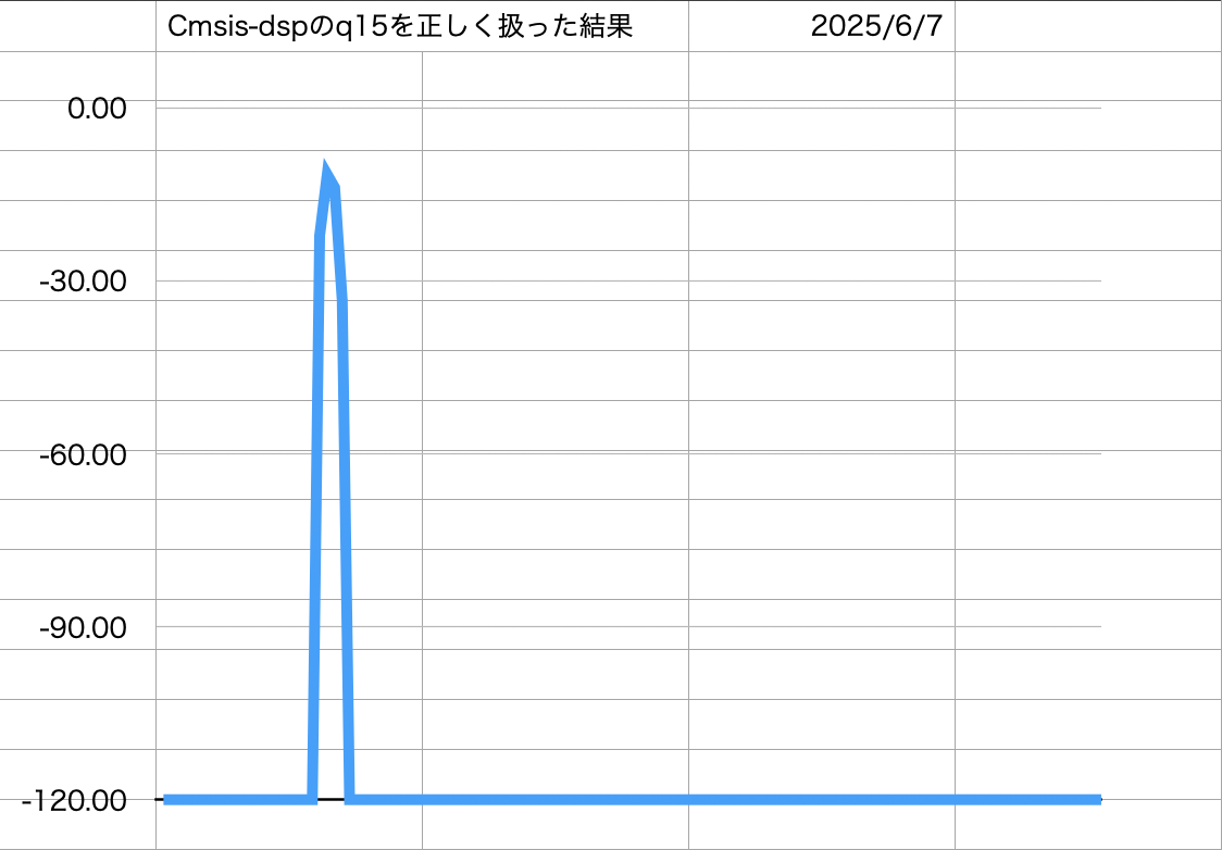
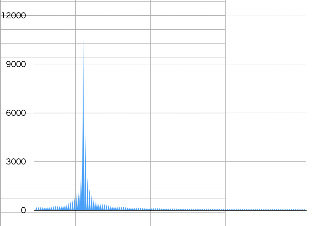
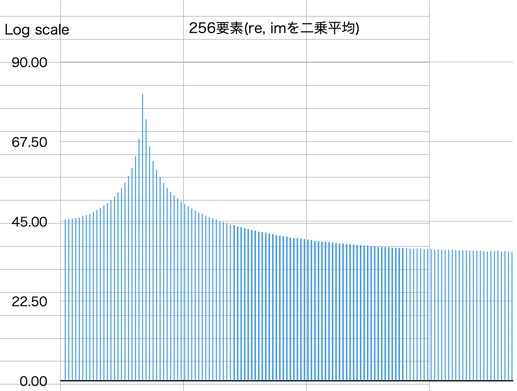
<FFTの実行結果>

デバッガからの読み出し値をプロットしてみた、奇数の高調波がきちんと検出できている
<現状のコード:WordPressのテキスト機能で貼り付けると崩れるので本文にしてます>
ADCのサンプリングとFFTは一回だけで打ち止め、デバッグ用にですが
/* See https://m0agx.eu/practical-fft-on-microcontrollers-using-cmsis-dsp.html */
//
// DMA transfer & interrupt handling version
//
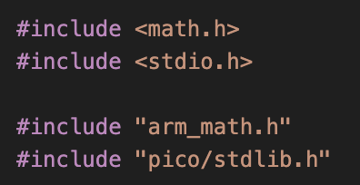
#include <math.h>
#include <stdio.h>
#include “arm_math.h”
#include “pico/stdlib.h”
#include “pico/time.h”
#include “hardware/sync.h”
// For ADC input & IRQ:
#include “hardware/adc.h”
#include “hardware/dma.h”
#include “hardware/irq.h”
// use multi core
#include “pico/multicore.h”
#include “hardware/pio.h”
#include “hardware/pwm.h”
void core1_main();
#define FFT_SIZE 256
// Channel 0 is GPIO26 for ADC sampling
#define CAPTURE_CHANNEL 0
int dma_chan;
uint32_t start_time;
uint32_t end_time;
q15_t fft_output[FFT_SIZE * 2]; // 出力(複素数 interleaved)
q15_t mag_squared[FFT_SIZE]; // パワースペクトル(Q13形式)
q15_t hann_window[FFT_SIZE];
arm_rfft_instance_q15 fft_instance;
#define RAW_SAMPLES 2560
#define DOWNSAMPLED 256
#define DECIMATE_N 10
uint16_t capture_buf[RAW_SAMPLES];
q15_t filtered_downsampled[DOWNSAMPLED];
static inline q15_t lowpass_filter_q15(q15_t input, q15_t prev, q15_t alpha)
{
int32_t one_minus_alpha = 32768 – alpha; // Q15で (1 – α)
int32_t filtered = ((int32_t)input * alpha + (int32_t)prev * one_minus_alpha) >> 15;
return (q15_t)__SSAT(filtered, 16);
}
void filter_and_downsample()
{
q15_t prev = 0; // IIRの初期値
q15_t alpha = 8192; // Q15形式の係数(約 0.25)
int down_idx = 0;
for (int i = 0; i < RAW_SAMPLES; i++)
{
// ADC raw は 12bit(0~4095)想定 → 中心化&スケーリング
int32_t centered = (int32_t)capture_buf[i] – 2048;
q15_t sample = (q15_t)__SSAT(centered << 3, 16); // ≒ Q15スケーリング Clipping would not happen in this case
// IIR フィルタ適用
prev = lowpass_filter_q15(sample, prev, alpha);
// N点ごとに出力へ保存
if ((i % DECIMATE_N) == 0 && down_idx < DOWNSAMPLED)
{
filtered_downsampled[down_idx++] = prev;
}
}
}
// FFT & Power calc
void perform_fft_and_power_spectrum(arm_rfft_instance_q15 *instance, q15_t *input, q15_t *output, q15_t *power_spectrum)
{
arm_rfft_q15(instance, input, output);
arm_cmplx_mag_squared_q15(output, power_spectrum, FFT_SIZE);
}
// ADC DMA transfer set up
void adc_dma_init()
{
// Init GPIO for analogue use: hi-Z, no pulls, disable digital input buffer.
adc_gpio_init(26 + CAPTURE_CHANNEL);
adc_init();
adc_select_input(CAPTURE_CHANNEL);
adc_fifo_setup(
true, // Write each completed conversion to the sample FIFO
true, // Enable DMA data request (DREQ)
1, // DREQ (and IRQ) asserted when at least 1 sample present
false, // We won’t see the ERR bit because of 8 bit reads; disable.
false // not Shift each sample to 8 bits when pushing to FIFO
);
adc_set_clkdiv(1.0f);
sleep_ms(1000);
// Set up the DMA to start transferring data as soon as it appears in FIFO
dma_chan = dma_claim_unused_channel(true);
dma_channel_config cfg = dma_channel_get_default_config(dma_chan);
// Reading from constant address, writing to incrementing byte addresses
channel_config_set_transfer_data_size(&cfg, DMA_SIZE_16);
channel_config_set_read_increment(&cfg, false);
channel_config_set_write_increment(&cfg, true);
// Pace transfers based on availability of ADC samples
channel_config_set_dreq(&cfg, DREQ_ADC);
dma_channel_configure(dma_chan, &cfg,
capture_buf, // dst
&adc_hw->fifo, // src
RAW_SAMPLES, // transfer count
false // start when triggered
);
dma_channel_set_irq0_enabled(dma_chan, true);
adc_run(true);
}
// to apply Hann window & call FFT/Power calc
void fft_exec()
{
// q15_t input[FFT_SIZE];
q15_t windowed_input[FFT_SIZE];
float hann_correction = 1.0f / 0.5f; // ハニング窓で約0.5倍になる補正
start_time = time_us_32();
for (int n = 0; n < FFT_SIZE; n++)
{
int32_t val = filtered_downsampled[n] * hann_window[n];
windowed_input[n] = (q15_t)(val >> 15);
}
perform_fft_and_power_spectrum(&fft_instance, windowed_input, fft_output, mag_squared);
end_time = time_us_32();
//printf(“Execution time: %.2f us per FFT\n”, (float)(end_time – start_time));
float q13_to_float = 1.0f / 8192.0f; // Q13 → float
for (uint32_t j = 0; j <= FFT_SIZE / 2; j++)
{
float mag_q13 = (float)mag_squared[j] * q13_to_float;
float mag_corr = mag_q13 * hann_correction; // Hanning補正(約2倍)
float voltage_rms = sqrtf(mag_corr);
float db = 20.0f * log10f(voltage_rms + 1e-6f);
printf(“Bin %3u: %.2f dB\n”, j, db);
}
}
// IRQ handler
void dma_handler()
{
// stop ADC sampling
adc_run(false);
// Clear the interrupt request.
dma_hw->ints0 = 1u << dma_chan;
filter_and_downsample();
// Give the channel a new wave table entry to read from, and re-trigger it
dma_channel_set_read_addr(dma_chan, &adc_hw->fifo, false);
dma_channel_set_write_addr(dma_chan, capture_buf, false);
dma_channel_set_trans_count(dma_chan, RAW_SAMPLES, false);
dma_channel_start(dma_chan);
// adc_run(true); // make it oneshot only for debug purpose
// exec FFT process in parallel with ADC DMA transfer
fft_exec();
}
#define OUTPUT_PIN 2
void setup_pwm()
{
gpio_set_function(OUTPUT_PIN, GPIO_FUNC_PWM);
uint slice_num = pwm_gpio_to_slice_num(OUTPUT_PIN);
pwm_config config = pwm_get_default_config();
pwm_config_set_clkdiv(&config, 1.0f); // PWM clock = 125 MHz / 1 = 125 MHz
// 周期 = 25,000クロック → 2.5kHz(= 125M / 50.0k)
pwm_config_set_wrap(&config, 49999);
pwm_init(slice_num, &config, true);
// デューティー比 = 50%
pwm_set_gpio_level(OUTPUT_PIN, 25000);
}
int main()
{
stdio_init_all();
sleep_ms(1000);
setup_pwm();
multicore_launch_core1(core1_main);
// initialize the ADC buffer
adc_dma_init();
// to prepare Hanning window coefficient
for (int n = 0; n < FFT_SIZE; n++)
{
float hann = 0.5f * (1.0f – cosf(2.0f * M_PI * n / (FFT_SIZE – 1)));
hann_window[n] = (q15_t)(hann * 32767.0f);
}
// initialise FFT instance
arm_status status = arm_rfft_init_q15(&fft_instance, FFT_SIZE, 0, 1);
// to register IRQ handler and enable it
irq_set_exclusive_handler(DMA_IRQ_0, dma_handler);
irq_set_enabled(DMA_IRQ_0, true);
// first ADC sampling start
adc_run(false);
dma_channel_start(dma_chan);
adc_run(true);
// wait forever
__wfi();
//__BKPT(1);
}
// —————————————————————————-
// core1 will be used for LCD display control
void core1_main()
{
}
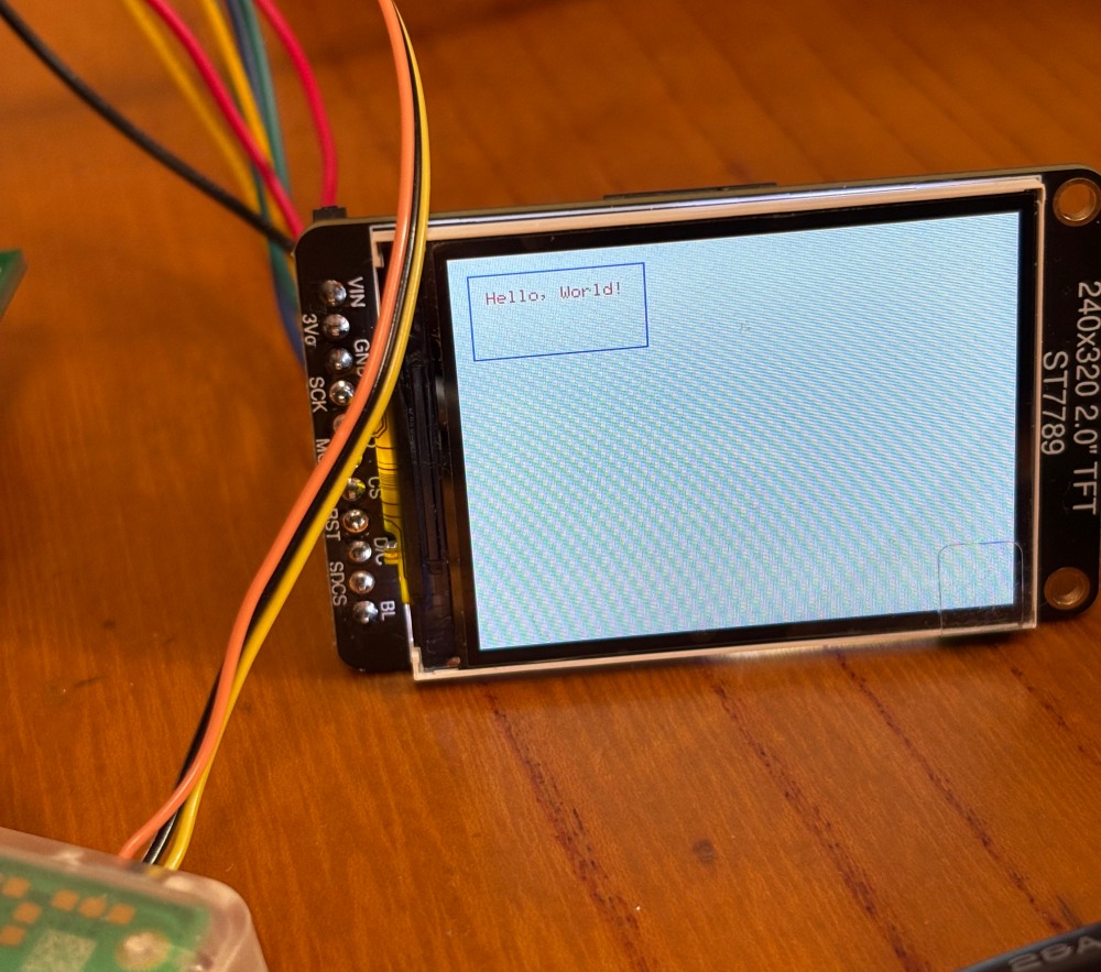
表示部分(ミニLCD)の検討しないと、信号の前処理(最小限オペアンプでの処理)も必要ですが、
admin