経緯を整理すると、
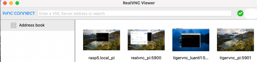
① 途中にMacBookのrebootが入っていたと思うけど、立ち上げてもVNCに接続できないのが起点
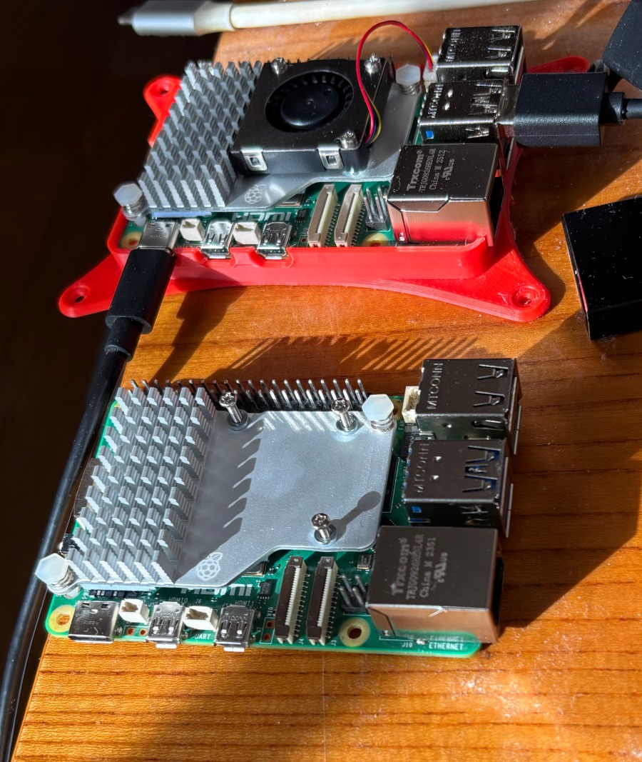
② boot時の動作確認用のファンも回転しないので壊れたと認識して新規購入
新規購入品での挙動不審だったので色々やったけど、結局問題は、
① ラズパイ5のEEPROMが破損してたらしい(EEPROM書き込みSSDで復旧、書き換えSDで起動時の緑LEDの点滅では分かりづらいから時間待ちが確実)
新規購入品でもSDとUSB SSDを切り替えたら、また壊れたのでUSB SSDだけで運用
② VPN(tail scale)はMacBookの再起動でdown状態になるようだ、tail scale upしてるかはmagic DNS(例えば ssh pi@rasp5、rasp5.localじゃなく、を受け付ければup状態)でも状態は確認できる、tailscale statusでも良いけどね、
Expiry disabledで設定してもそのデバイスが削除されないだけで、upしていることとは別だよということ
①の発生原因は今のところ不明、回避方法はどちらかの媒体のみ挿入して、起動時の選択を無くする、書き換え用のSDカード常備というのは必要そうである
以上の結果から、もしやと思って古い方のラズパイ5にEEPROM書き換え実行して、tailscale up状態でVNC接続、つまり正常動作、を確認できたから実は壊れたと勘違いしてたようだ
②の永続化(rebootで自動up)するためには、
brew install --formula tailscale
sudo brew services start tailscale
sudo tailscale up
最後のupでwarning出るけど無視して良いようだ、sudo tailscale upでsudoが必要なのはデーモンモードだから、アプリ版ならsudoは不要
% sudo tailscale up
Warning: client version "1.94.2-t2de4d317a" != tailscaled server version "1.94.2-t0a29cf18b-g3f044c9f6"
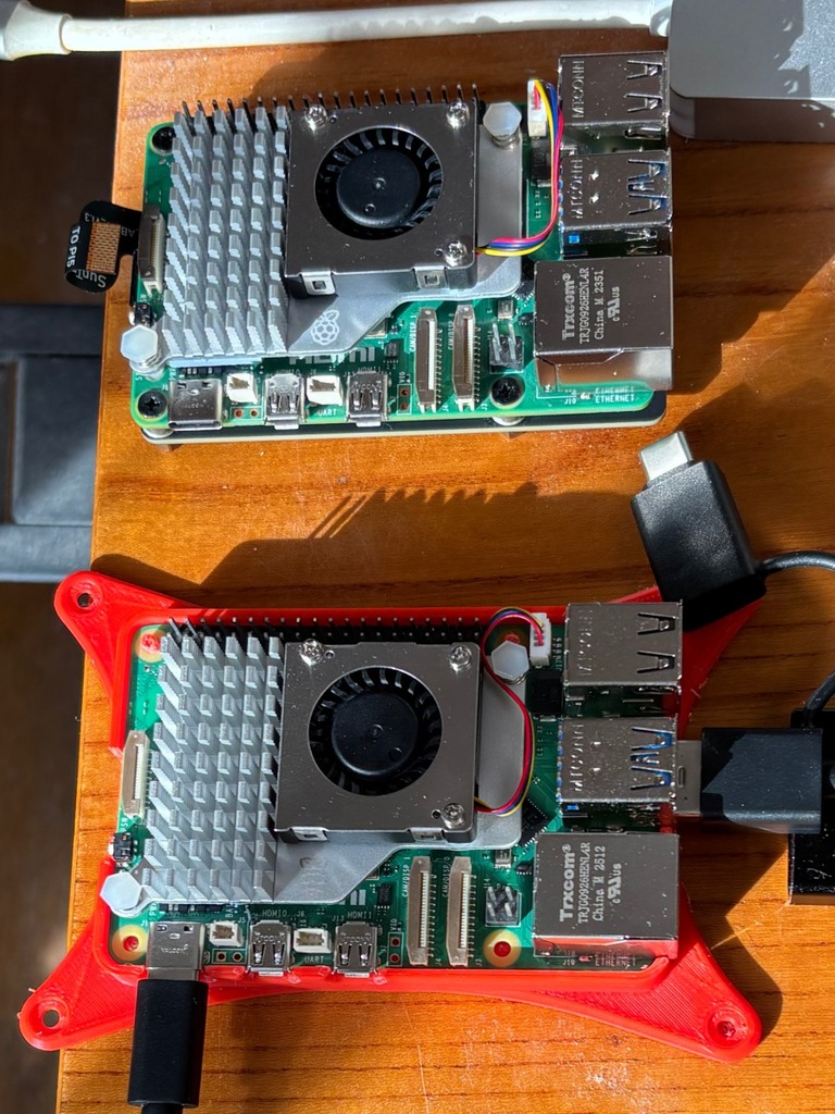
予備機ができたから使い道考えよう、ヘッドレス運用というのはネットワーク経由とオンボードのLEDしか稼働状態判らないのがネック
admin