そろそろ夏も本番に近づいて、散歩も一時間が限界になりますが、暑さを客観的な数値にするにはWGBT指数(湿度と温度で判定)ですが、無論風のあるなし、直射日光下、人間の暑さ耐性、あるいは運動強度によって変わってくるので目安の数値ですが、i2cインターフェースの温湿度(気圧もある)センサーとM5stackで実現します。M5stackも電源入れっぱなしでなくて、時々チェックするぐらいなら電池120mAhでも使えると思う。
・用意したもの
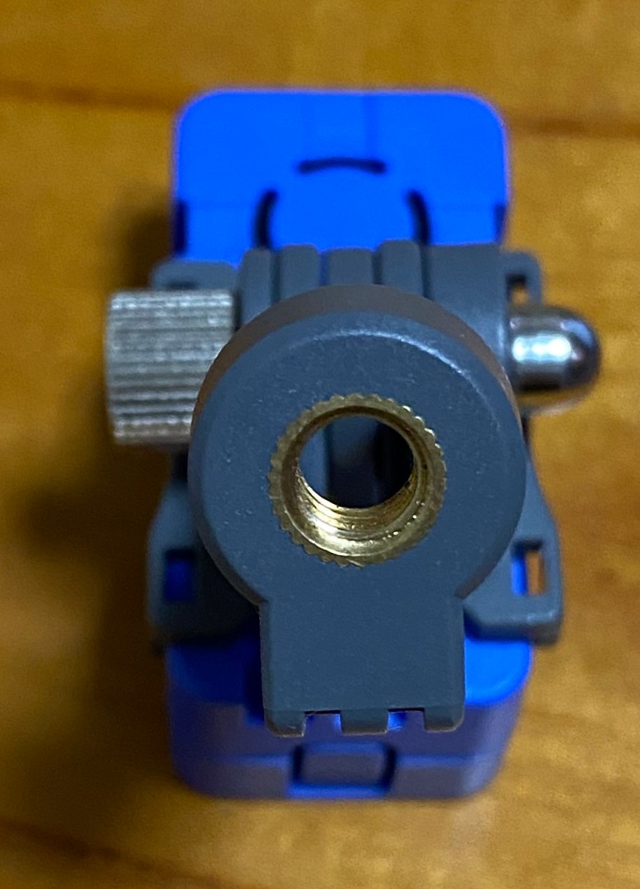
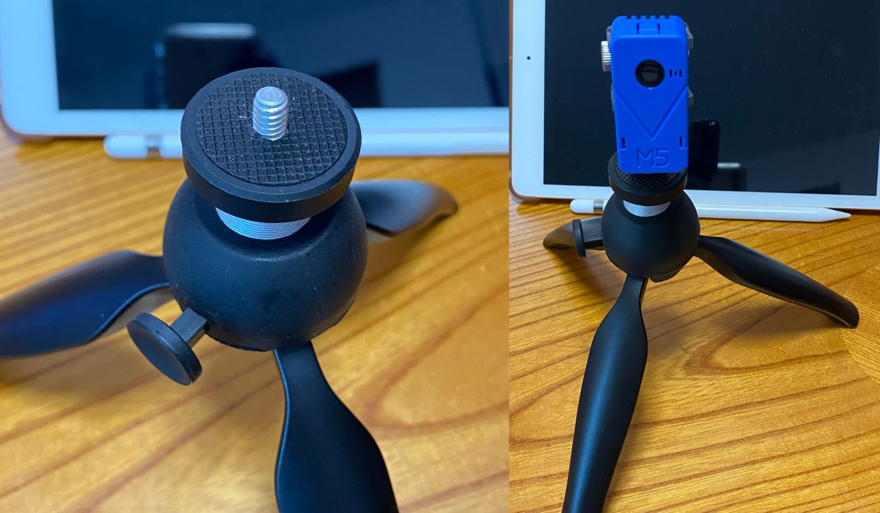
M5Stack Basic V2.6
M5Stack用温湿度気圧センサユニット Ver.3(ENV Ⅲ)
いずれもいつものスイッチサイエンスで購入。
センサーのライブラリとサンプルコードは以下からダウンロード。
・サンプルコード@GitHub
https://github.com/m5stack/UNIT_ENV/blob/master/examples/UNIT_ENV_III_M5Stack/UNIT_ENV_III_M5Stack.ino
・unit_env
以下をVScodeのソースディレクトリに展開します。
https://github.com/m5stack/UNIT_ENV
・USBドライバー
M5stackへのバイナリのアップロードで以下のようなエラー発生、これはM5Stack Basic V2.6でUSB-serialのICが変わっていて、標準のOSではまだサポートしていないからだと、スイッチサイエンスのページにも記載あります。
Uploading stub…
A fatal error occurred: Failed to write to target RAM (result was 01070000: Operation timed out)
*** [upload] Error 2
しかし、
https://mag.switch-science.com/2021/11/01/m5stack-v2-6-changes/
に書いてある様にやってみてもダメで、
platformio.iniに以下のようなポート決めうち指定で解決しました。

“monitor_speed = 115200″と合わせて、platformio.iniへのデフォルト設定になると思います。
ポート番号は環境で変わると思うので、wch以降は、
/devディレクトリで
% ls tty.wch* を実行して確認しましょう。PIO HomeのDevicesではそのままの値が確認できますが。
tty.wchusbserial54260147311
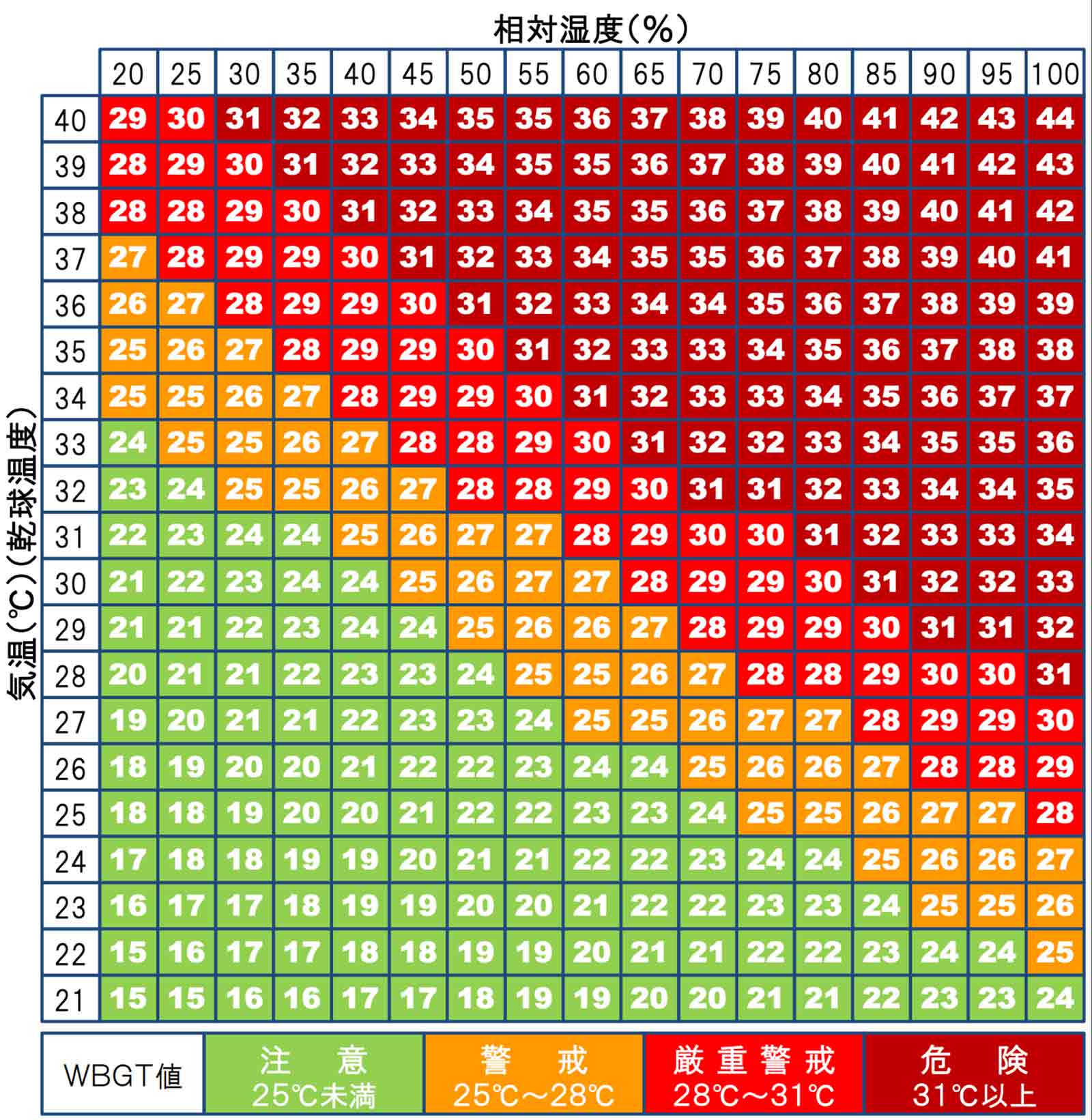
・WBGT指数
https://healthy-ecohouse.com/wp-content/uploads/2019/08/190804-4.jpg
からダウンロード
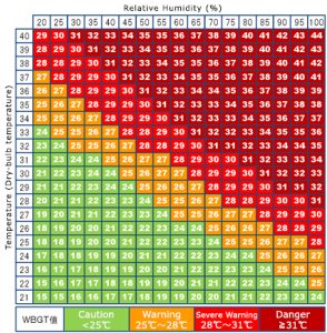
このテーブルをソースの中に二次元配列で埋め込んで、WBGT値を獲得しています。
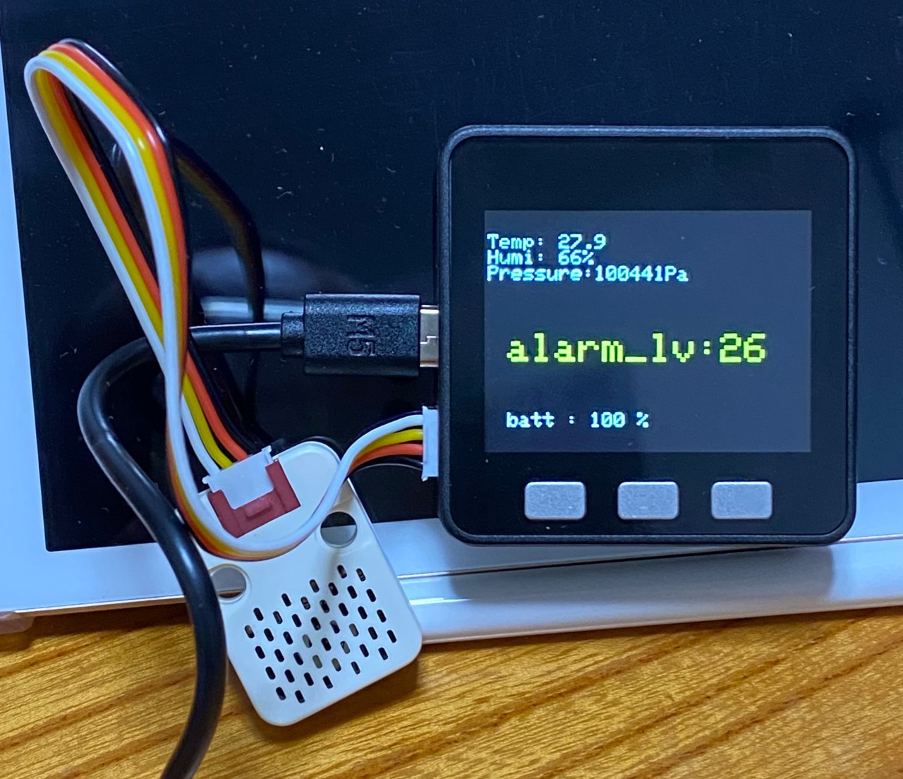
画面はこんな感じです。

全部のコードは、
https://github.com/chateight/PlatformIO/tree/master/heat_alarm/src
heat_alarm.cpp以外はセンサーアクセス用のライブラリファイルです。
P.S. @2022/6/22
表示方法変更しました、テキストよりもカラーブロックで表示がわかりやすいから。
気圧の使い道は何なのかなと考えると、一番分かりやすいのは標高を簡易的に知るということになると思う。およそ100m高くなると10hPa気圧は低下するのだから。
P.S.2 @2022/6/25
ということで、大まかな高度も表示するようにしました。気圧は揺れ動くから、刻みは200m刻みで山に行ったときぐらいには使えるレベル。正確に出すならばGPSモジュール使うのだろうけど、そこまでは不要でセンサーの機能があるから使ってみようぐらいの話。
admin


