VScodeのラズピコエクステンション(Raspberry Pi Pico)にいくつかのサンプルコードがあるのでその中から内蔵ADCからDMA転送するコードがあるので、ついでにADCの精度も見てみた
<環境>
M4 MacBook, VScode、ラズピコエクステンション(Raspberry Pi Pico)使用
<変更箇所>
・結果を4bitシフトで8bitにしてるのを12bit獲得する
・ADC読み出し値の最大値と平均値を求める処理追加(GPIO26はGND接続)
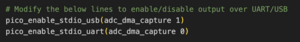
・USBシリアルを使えるようにCMakeに追加(但し動作がイマイチ不安定、予想外の時に出力されて、期待した時は出力されない、なのでデバッガに期待)
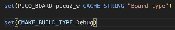
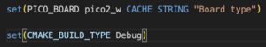
・コンパイラが最適化すると見れないローカル変数があるので、変数が見れるようにDebugモードにするようにCMakeで設定
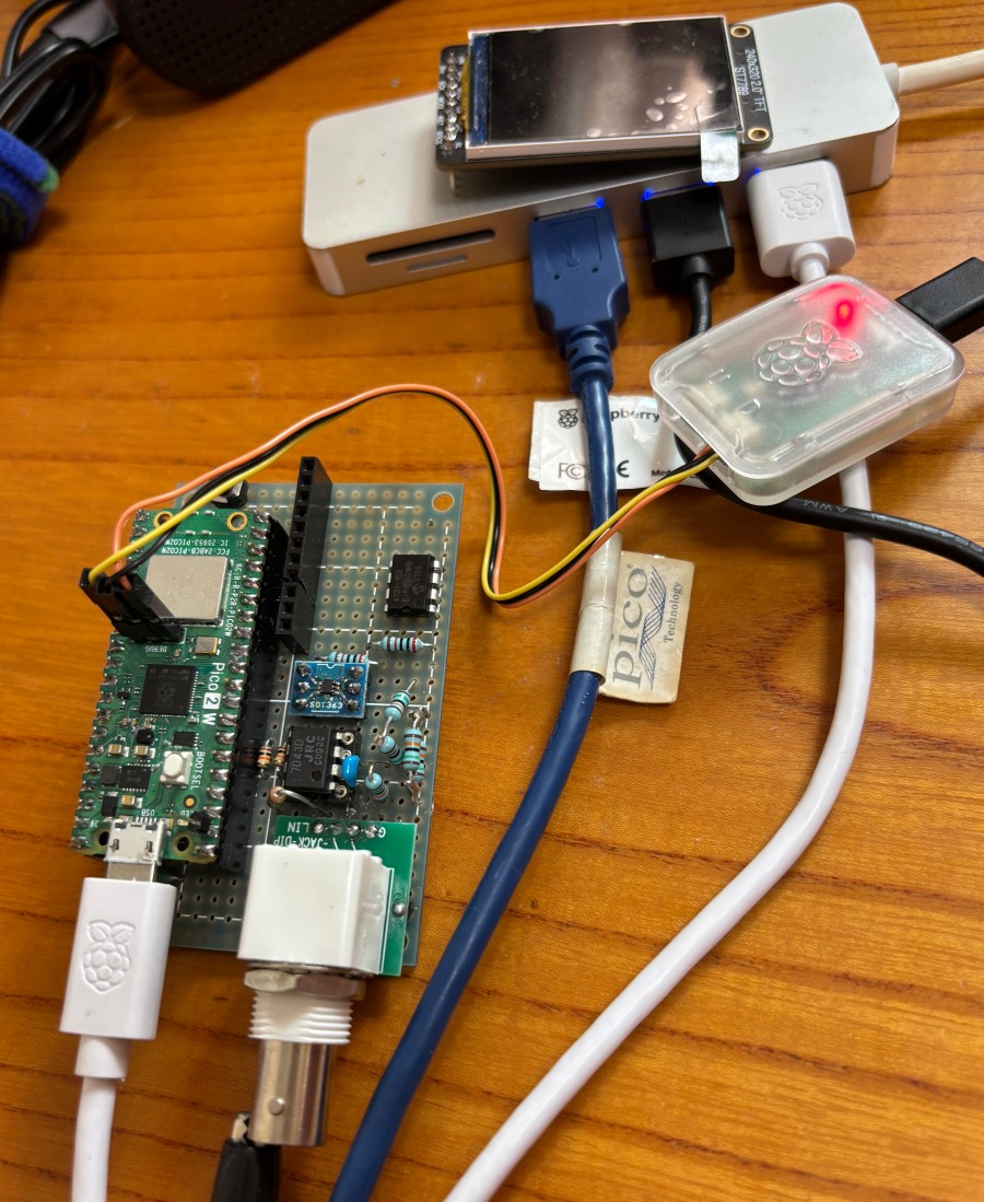
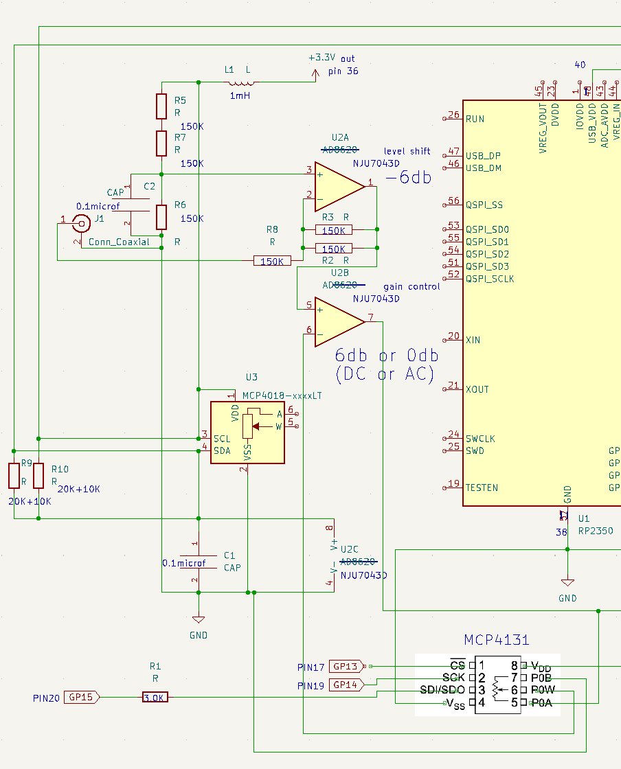
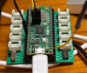
<接続>
こんな感じでGNDに落とす、
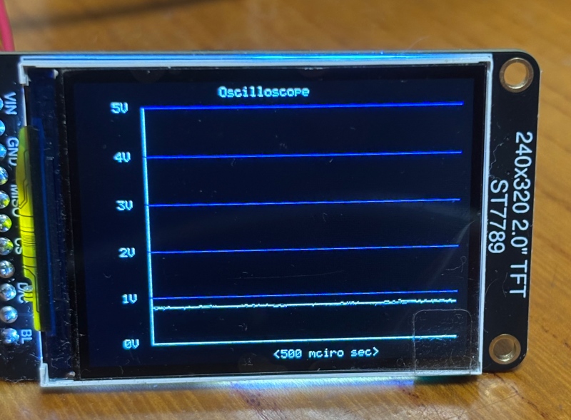
<結果>
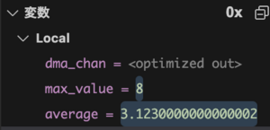
予想通り、LSB側の3ビットぐらいはノイズに埋もれてる
<全体のコード>
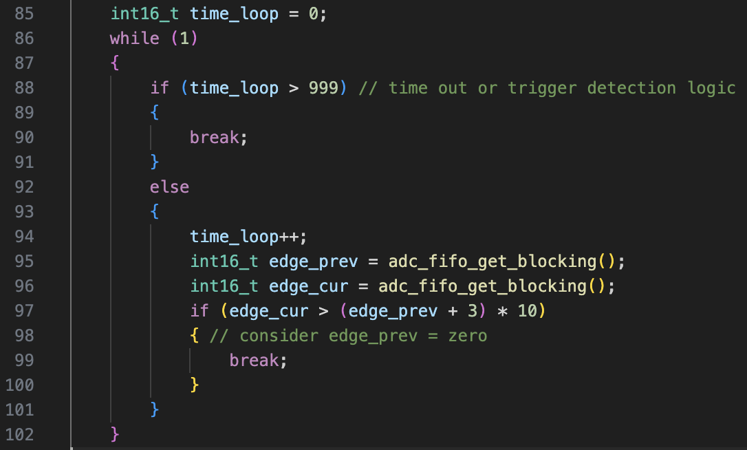
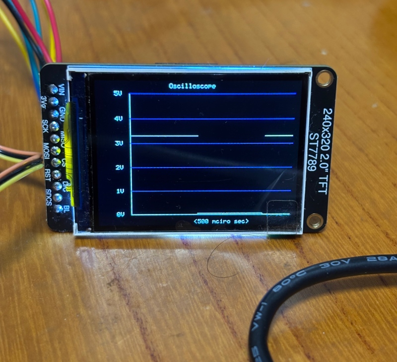
core1側で三角波作って外部のDACで波形作成して、ADCに入力することを想定しているね
DMA処理自体はレジスタ操作とかは不要で、pico-sdkに関数が用意されている
/**
 * Copyright (c) 2021 Raspberry Pi (Trading) Ltd.
 *
 * SPDX-License-Identifier: BSD-3-Clause
 */
//
// ADC values are 4bits shifted, so the max value is 255
//
// -> modify to handle full scale 12bits(2025/6/4)
// it seems noisy, LSB 3bits are inaccrate
//
#include <stdio.h>
#include "pico/stdlib.h"
// For ADC input:
#include "hardware/adc.h"
#include "hardware/dma.h"
// For resistor DAC output:
#include "pico/multicore.h"
#include "hardware/pio.h"
#include "resistor_dac.pio.h"

// This example uses the DMA to capture many samples from the ADC.
//
// - We are putting the ADC in free-running capture mode at 0.5 Msps
//
// - A DMA channel will be attached to the ADC sample FIFO
//
// - Configure the ADC to right-shift samples to 8 bits of significance, so we
//   can DMA into a byte buffer
//
// This could be extended to use the ADC's round robin feature to sample two
// channels concurrently at 0.25 Msps each.
//
// It would be nice to have some analog samples to measure! This example also
// drives waves out through a 5-bit resistor DAC, as found on the reference
// VGA board. If you have that board, you can take an M-F jumper wire from
// GPIO 26 to the Green pin on the VGA connector (top row, next-but-rightmost
// hole). Or you can ignore that part of the code and connect your own signal
// to the ADC input.

// Channel 0 is GPIO26
#define CAPTURE_CHANNEL 0
#define CAPTURE_DEPTH 1000

uint16_t capture_buf[CAPTURE_DEPTH];


void calc_max_and_avg(const uint16_t *buf, size_t len, uint16_t *max_val, double *avg_val) {
    uint16_t max = 0;
    uint32_t sum = 0;
    for (size_t i = 0; i < len; ++i) { if (buf[i] > max) max = buf[i];
        sum += buf[i];
    }
    *max_val = max;
    *avg_val = (double)sum / len;
}


void core1_main();

int main() {
    stdio_init_all();

    // Send core 1 off to start driving the "DAC" whilst we configure the ADC.
    multicore_launch_core1(core1_main);

    // Init GPIO for analogue use: hi-Z, no pulls, disable digital input buffer.
    adc_gpio_init(26 + CAPTURE_CHANNEL);

    adc_init();
    adc_select_input(CAPTURE_CHANNEL);
    adc_fifo_setup(
        true,    // Write each completed conversion to the sample FIFO
        true,    // Enable DMA data request (DREQ)
        1,       // DREQ (and IRQ) asserted when at least 1 sample present
        false,   // We won't see the ERR bit because of 8 bit reads; disable.
        false    // not Shift each sample to 8 bits when pushing to FIFO
    );

    // Divisor of 0 -> full speed. Free-running capture with the divider is
    // equivalent to pressing the ADC_CS_START_ONCE button once per `div + 1`
    // cycles (div not necessarily an integer). Each conversion takes 96
    // cycles, so in general you want a divider of 0 (hold down the button
    // continuously) or > 95 (take samples less frequently than 96 cycle
    // intervals). This is all timed by the 48 MHz ADC clock.
    adc_set_clkdiv(0);

    printf("Arming DMA\n");
    sleep_ms(1000);
    // Set up the DMA to start transferring data as soon as it appears in FIFO
    uint dma_chan = dma_claim_unused_channel(true);
    dma_channel_config cfg = dma_channel_get_default_config(dma_chan);

    // Reading from constant address, writing to incrementing byte addresses
    channel_config_set_transfer_data_size(&cfg, DMA_SIZE_16);
    channel_config_set_read_increment(&cfg, false);
    channel_config_set_write_increment(&cfg, true);

    // Pace transfers based on availability of ADC samples
    channel_config_set_dreq(&cfg, DREQ_ADC);

    dma_channel_configure(dma_chan, &cfg,
        capture_buf,    // dst
        &adc_hw->fifo,  // src
        CAPTURE_DEPTH,  // transfer count
        true            // start immediately
    );

    printf("Starting capture\n");
    adc_run(true);

    // Once DMA finishes, stop any new conversions from starting, and clean up
    // the FIFO in case the ADC was still mid-conversion.
    dma_channel_wait_for_finish_blocking(dma_chan);
    printf("Capture finished\n");
    adc_run(false);
    adc_fifo_drain();   // max four samples

    // Print samples to stdout so you can display them in pyplot, excel, matlab
    for (int i = 0; i < CAPTURE_DEPTH; ++i) {
        printf("%u, ", capture_buf[i]);
        if (i % 10 == 9)
            printf("\n");
    }

    uint16_t max_value;
    double average;

    calc_max_and_avg(capture_buf, CAPTURE_DEPTH, &max_value, &average);

    printf("Max: %u\n", max_value);
    printf("Average: %f\n", average);
}

// ----------------------------------------------------------------------------
// Code for driving the "DAC" output for us to measure

// Core 1 is just going to sit and drive samples out continuously. PIO provides
// consistent sample frequency.

#define OUTPUT_FREQ_KHZ 5
#define SAMPLE_WIDTH 5
// This is the green channel on the VGA board
#define DAC_PIN_BASE 6

void core1_main() {
    PIO pio = pio0;
    uint sm = pio_claim_unused_sm(pio0, true);
    uint offset = pio_add_program(pio0, &resistor_dac_5bit_program);
    resistor_dac_5bit_program_init(pio0, sm, offset,
        OUTPUT_FREQ_KHZ * 1000 * 2 * (1 << SAMPLE_WIDTH), DAC_PIN_BASE);
    while (true) {
        // Triangle wave
        for (int i = 0; i < (1 << SAMPLE_WIDTH); ++i)
            pio_sm_put_blocking(pio, sm, i);
        for (int i = 0; i < (1 << SAMPLE_WIDTH); ++i)
            pio_sm_put_blocking(pio, sm, (1 << SAMPLE_WIDTH) - 1 - i);
    }
}
admin