sesameデバイスの種類が増えてきたので、電池の仕様のまとめ
sesameの電池型格
————————-
・セサミ5:CR123A
・セサミタッチ:CR2
・リモコン:CR2450*(1~3個)
・オープンセンサー:CR1632
セサミ5とセサミタッチはそこそこ大容量電池、消費電力多そうだし(一年ぐらいで見とくのが良さそう)、リモコン(電池3個で3年)はそこそこで、オープンセンサーはおそらくライフ中(10年有効とか)に電池交換の機会はなさそうだ
admin

la vie libre
sesameデバイスの種類が増えてきたので、電池の仕様のまとめ
sesameの電池型格
————————-
・セサミ5:CR123A
・セサミタッチ:CR2
・リモコン:CR2450*(1~3個)
・オープンセンサー:CR1632
セサミ5とセサミタッチはそこそこ大容量電池、消費電力多そうだし(一年ぐらいで見とくのが良さそう)、リモコン(電池3個で3年)はそこそこで、オープンセンサーはおそらくライフ中(10年有効とか)に電池交換の機会はなさそうだ
admin
この機能に、フロントエンド(アナログ信号の前処理)追加、
https://isehara-3lv.sakura.ne.jp/blog/2025/07/02/オシロスコープのスイープとトリガ条件を追加/
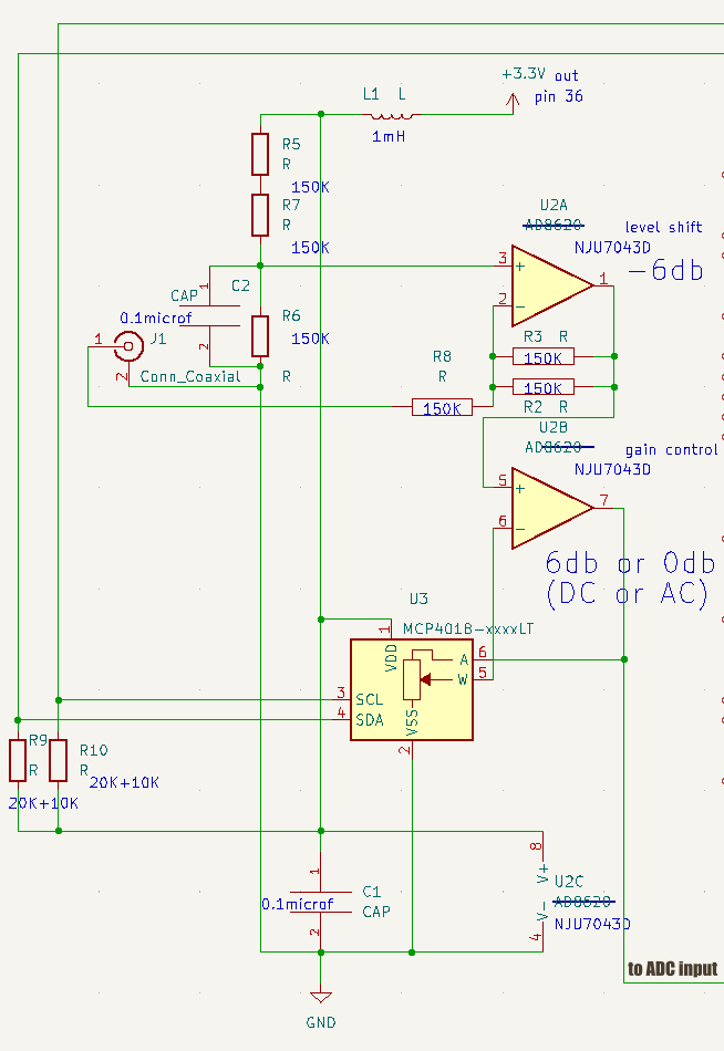
① AC入力のマイナス側も扱えるように、GNDレベルをVss/2 = 1.65 V付近にする、ゲインはフルスケール考慮して-6db
② 次の処理でゲイン6db(プラス方向にしか振れないパルス用)と0db(AC信号用)の選択をデジタルポテンショメーター使ってできるようにした(ただし、i2cバスで値を書き込んでもレスポンスまともだけだけど結果は無視された状態、つまり電源投入状態のwiperが中点状態のまま)、目的はADCの前にダイナミックレンジを確保したかったから
後の処理ではオシロスコープとするには、ADCから読み取った値が反転しているから元に戻す処理必要だけど、コードには未反映
https://github.com/chateight/dsp
回路図とi2cのタイムチャートをアップロードしてあります
admin
一ヶ月半使って、不自由に感じたところをアップデート、痒いとこに手が届く製品はちゃんと標準で用意されてます
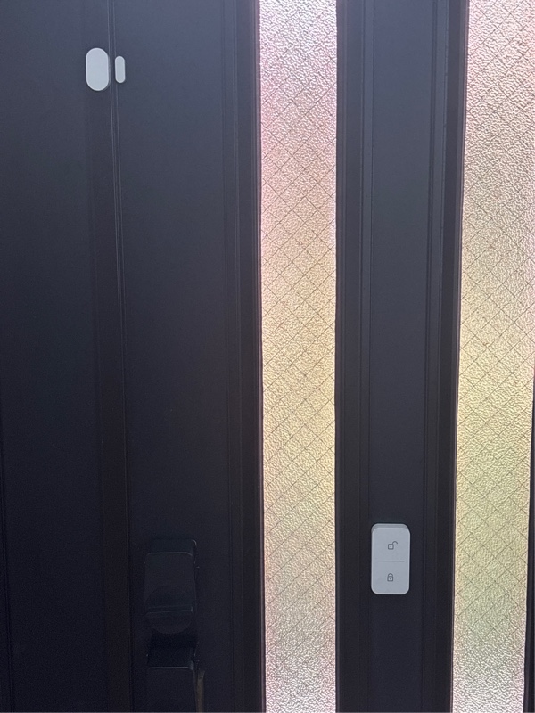
おそらくこの運用でしばらくは問題ないと思う、あとはドアアンロックで顔認証使うとかだけど、それは今のセサミタッチが壊れた時かな
P.S. リモコンオープナーの電池残量不安定(一週間経過後に60%とかになっていて、尚且つその値は不安定で90%以上に回復してる時もある)、sesameに問い合わせると改善検討中との回答、CR2450を3個使いにした方が安定そうだから電池追加で手配した、元々が電池3個入るようになっているのもそのための考慮のように思う
admin
概ねどんなオシロスコープにもある表示モードは、
・トリガーモード
・フリーランモード
・ワンショットモード
昨日までの実装はトリガーモードだけだったので、フリーランモードを追加した
該当部分のロジックは、以下のコード、
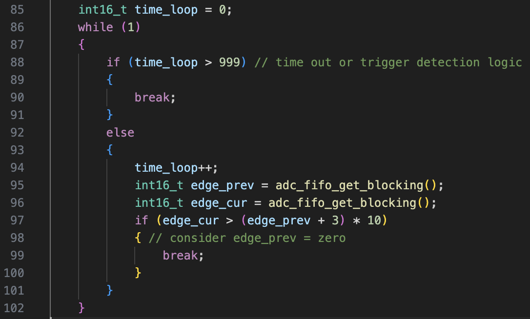
要はおよそ4ms(2μs*2*1000)の間にトリガー要件が発生しないと、そこからADCのデータ取得して表示しています
ワンショットモードは、トリガーモードで一度条件発生したら以降のトリガーは無効にするだけだろうから包含されていて設定だけの問題
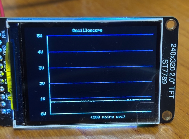
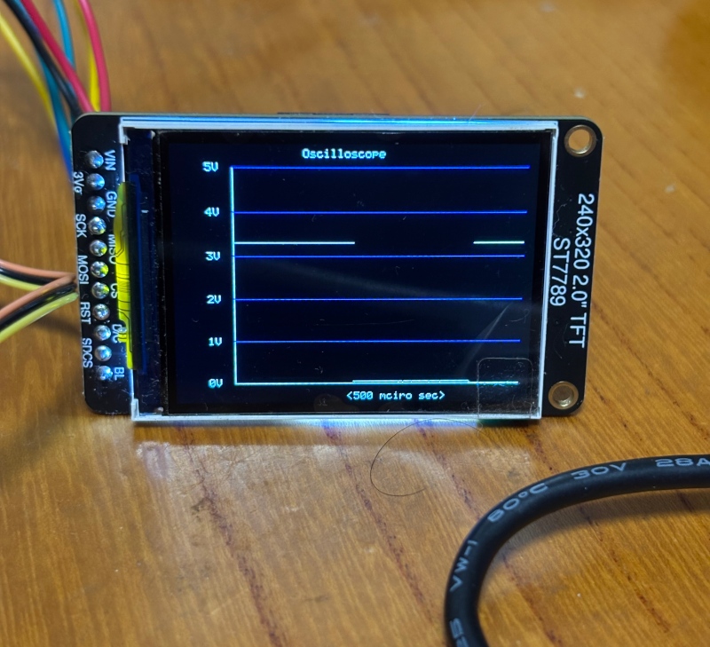
この機能を追加するだけで、普通のオシロスコープらしくなります
ADCの入力開放でフリーラン状態の写真、入力開放だと概ね0.8Vぐらいに見えるようです、何らかの入力保護回路は入っているんだろうけども
admin
周波数軸のスペアナに対して時間軸のオシロスコープ機能の実装、最終的には物理スイッチで機能切り替えだろうけど、今はソースコードに埋め込んだ変数で機能切り替え
ソースコードは以下になるけれども、スペアナコードをかなり流用
① ADCのサンプリングコード中に立ち上がりのエッジ検出ロジックを入れ込み(ほぼ方形波前提の検出ロジックになってます)
② LCDの表示バッファーは二面持たせて、変化分だけ描画はスペアナと同じだけどライン描画からドット描画だから相対的に高速のはず
以下は現状のコード
https://github.com/chateight/dsp
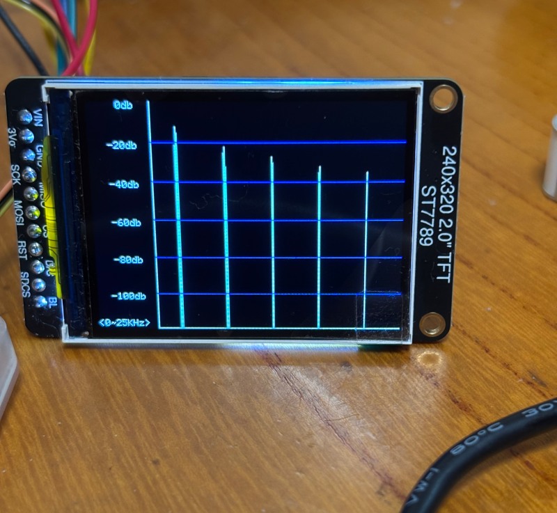
スペアナに入力しているおよそ2.3KHzの方形波を表示させたところ
・サンプル周期2μs(およそ500KHz)
・表示時間長はおよそ500μs(256フレーム*2μs)
admin
いくつか当初の思惑と違ったところ、
1. 結局ADCデータ読み取りのDMA処理終わった後の割り込みが2回目以降は発生しない、デバッガで止めながらだと発生するからタイミング問題だろ受けで原因突き止めできない
2. ADCのクロックデバイドはDMAモード以外でも有効化できない
従って、現状のロジックは、CPUが介在しておよそ500KHzで動くADCのデータを2μsごとに読み取って蓄積
以降の処理はDMA使った時と大差なし
3. LCDの表示処理は初回描画だけは画面全面書き込みになるけど、2回目以降は差分処理だけにして高速化、ただしフレーム周期は今の所およそ12ms*10 =120 ms にしている
4. 初回のLCD(全面書き込み)は500ms程度掛かっているから、FFTデータは一度表示用にコピーして、次のFFT処理で壊されないように別保存している、今は表示周期をおよそ120msぐらいにしているけども、2回目以降は変更部分のみの書き換えだから高速
この画像はおよそ2KHz(ちょっと下)の方形波をPWMから入力して9次の高調波まで表示されている状態
コード全体は、以下のリンクから
https://github.com/chateight/dsp
もちろん用途によるけど、ラズパイシリーズではラズピコが値段考えると一番使い出があるように思う
admin
LCDの動作確認のためにArduino IDEで動作確認(受入試験みたいなもので以下のリンク)しましたが、Cのライブラリ使わないとスペアナ計算と結合できないのでpico-sdk使ってやってみます
https://isehara-3lv.sakura.ne.jp/blog/2025/06/20/ラズピコでspiバス経由でlcd表示させる/
ライブラリは使い方がシンプルなので構造が単純な以下を使います
https://github.com/Imel23/lcd-st7789-library
ライブラリを使う時には、ハードワイヤリングの設定をソース上で行うこととSPIの動作モードを指定しないと動作しなかった(以下変更部分のコード)、それ以外には画面ローテーションの指定もしています、この記事の最後の方に記載
SPI clockは62.5MHzのままだと動作に不安があるので20MHzまで落としてます、どうせ62.5MHzでも最初の電源オンのチラつき(データが初期状態では不定だから)はあるから、バックライト信号の制御がいずれ必要
// Pin definitions for the LCD connection
//#define BL_PIN 13 // Backlight pin
#define DC_PIN 20   // Data/Command pin
#define RST_PIN 21  // Reset pin
#define MOSI_PIN 19 // SPI MOSI pin
#define SCK_PIN 18  // SPI Clock pin
#define CS_PIN 17   // Chip Select pin

// SPI configuration
#define SPI_PORT spi0
#define SPI_BAUDRATE 2000000  // 62.5 MHz SPI clock

// Function prototypes for internal use
static void lcd_write_command(uint8_t cmd);
static void lcd_write_data(uint8_t data);
static void lcd_set_window(uint16_t x1, uint16_t y1, uint16_t x2, uint16_t y2);

// Initialize the LCD
void lcd_init() {
    // Initialize SPI
    spi_init(SPI_PORT, SPI_BAUDRATE);
    spi_set_format(SPI_PORT, 8, SPI_CPOL_1, SPI_CPHA_1, SPI_MSB_FIRST);     // to add this line
ライブラリ用にcmakeファイルに設定を追加して、現状の中身は、
# Generated Cmake Pico project file

cmake_minimum_required(VERSION 3.13)

set(CMAKE_C_STANDARD 11)
set(CMAKE_CXX_STANDARD 17)
set(CMAKE_EXPORT_COMPILE_COMMANDS ON)

# Initialise pico_sdk from installed location
# (note this can come from environment, CMake cache etc)

# == DO NOT EDIT THE FOLLOWING LINES for the Raspberry Pi Pico VS Code Extension to work ==
if(WIN32)
    set(USERHOME $ENV{USERPROFILE})
else()
    set(USERHOME $ENV{HOME})
endif()
set(sdkVersion 2.1.1)
set(toolchainVersion 14_2_Rel1)
set(picotoolVersion 2.1.1)
#set(picoVscode ${USERHOME}/.pico-sdk/cmake/pico-vscode.cmake)
#if (EXISTS ${picoVscode})
#    include(${picoVscode})
#endif()
# ====================================================================================
set(PICO_BOARD pico2_w CACHE STRING "Board type")

set(PICO_SDK_PATH "$ENV{HOME}/pi/pico/pico-sdk")
#set(PICO_SDK_PATH "/Users/usamiryuuichi/pi/pico/pico-sdk")


# Pull in Raspberry Pi Pico SDK (must be before project)
include(pico_sdk_import.cmake)

project(dsp C CXX ASM)

# Initialise the Raspberry Pi Pico SDK
pico_sdk_init()

# Create a library for the LCD driver
add_library(lcd_driver STATIC
    lcd_st7789_library.c
    font_5x7.c
)

add_library(CMSISDSP STATIC IMPORTED GLOBAL)
set_target_properties(CMSISDSP PROPERTIES IMPORTED_LOCATION
  $ENV{HOME}/pi/pico/CMSISDSP/build/bin_dsp/libCMSISDSP.a)

#target_link_libraries(dsp CMSISDSP ...)

# Add executable. Default name is the project name, version 0.1

add_executable(dsp dsp.c )

pico_set_program_name(dsp "dsp")
pico_set_program_version(dsp "0.1")

# Modify the below lines to enable/disable output over UART/USB
pico_enable_stdio_uart(dsp 0)
pico_enable_stdio_usb(dsp 1)

# Add the standard library to the build
target_link_libraries(dsp
        pico_stdlib
        pico_multicore
        hardware_adc
        hardware_dma
        hardware_pio
        hardware_pwm
        hardware_spi
        CMSISDSP
        lcd_driver
        hardware_timer
        pico_multicore
)

target_link_libraries(lcd_driver
    pico_stdlib
    hardware_spi
)

# Add the standard include files to the build
target_include_directories(dsp PRIVATE
        ${CMAKE_CURRENT_LIST_DIR}
        $ENV{HOME}/pi/pico/CMSISDSP/CMSIS-DSP/Include
        $ENV{HOME}/pi/pico/CMSISDSP/CMSIS_6/CMSIS/Core/Include
        ${PICO_SDK_PATH}/src/rp2
)

target_include_directories(lcd_driver PRIVATE
    ${CMAKE_CURRENT_LIST_DIR}
    ${PICO_SDK_PATH}/src/common
    ${PICO_SDK_PATH}/src/rp2
)

pico_add_extra_outputs(dsp)
ディレクトリ構成は、
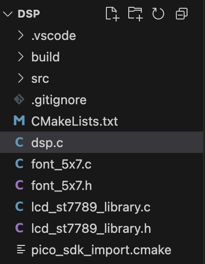
スペアナのコードに追加したのは、動作確認のためだけですが、
// core1 will be used for LCD display control
#include "pico/stdlib.h"
#include "lcd_st7789_library.h"
#include "hardware/spi.h"

void core1_main()
{
    // Initialize the LCD
    lcd_init();

    // Fill the screen
    lcd_fill_color(create_color(255, 255, 255));

    // Draw a rectangle
    lcd_draw_rect(10, 10, 100, 50, create_color(0, 0, 255));

    // Draw some text
    lcd_draw_text(20, 20, "Hello, World!", create_color(255, 0, 0), create_color(255, 255, 255), 1); // char color, bg color, font size

    while (1)
    {

    }
}
実行結果は、
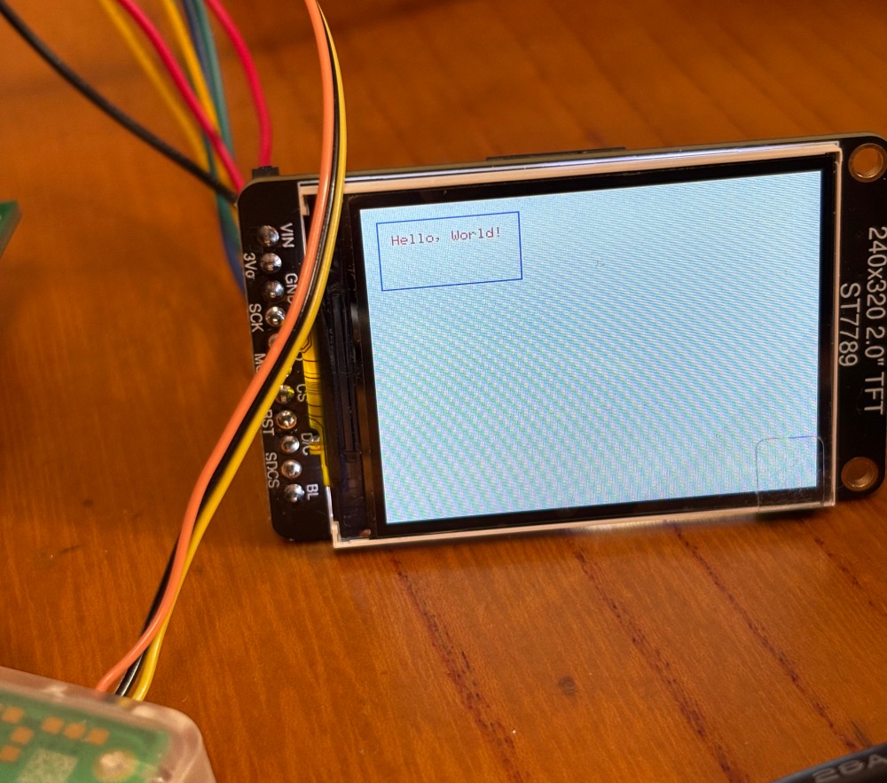
ローテーション指定はライブラリ中のここで、関数もあるようですが関数で後から指定すると表示が二重になった
    lcd_write_command(0x36);  // Memory Data Access Control
    lcd_write_data(0xA0);     // display rotation
admin
スペアナプロジェクト用ですが、2インチのLCD(240*320 dots)を購入、SDカードのアクセスもできるようになってますが
https://learn.adafruit.com/2-0-inch-320-x-240-color-ips-tft-display/pinouts
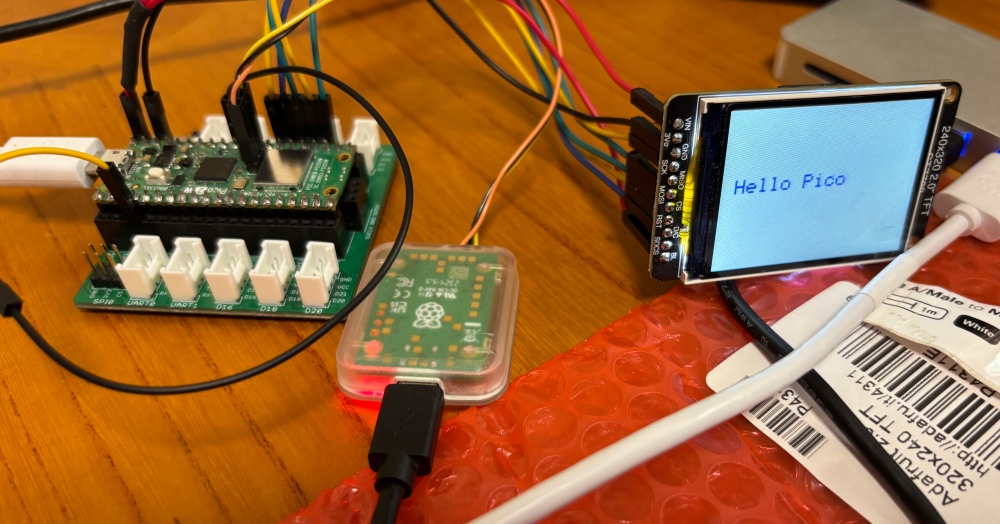
動作確認はArduino IDE使って、ライブラリは、
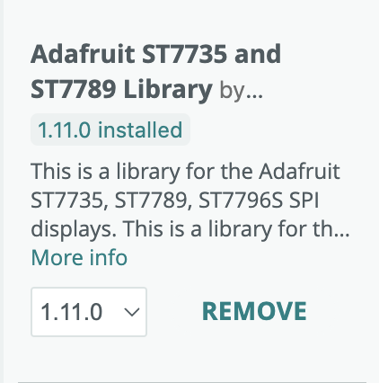
をインストします
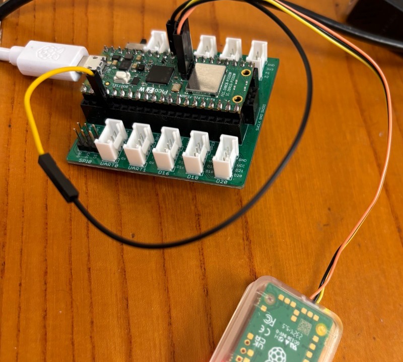
接続は以下のソースコードの通りですが、電源はピコの3.3V出力から取ろうとすると過電流(おそらくピコの電源電圧低下して動作不能状態になってる)でUF2ファイルのダウンロードできないので、USB電源であるVBUSから取らないと機能しなかった
電源電圧とバックライト制御信号(PWM)をまとめてVBUSに接続しています、従ってバックライトの輝度はmax状態ということ、GNDは一本なのでピコ – LCD間の接続は全部で8本です
<テスト用コード>
#include <adafruit_gfx.h>
#include <adafruit_st7789.h>
#include <spi.h>

// ピン定義(PicoのGPIO番号)
#define TFT_CS    17  // pin 22
#define TFT_RST   21  // pin 27
#define TFT_DC    20  // pin 26
#define TFT_SCK   18  // pin 24
#define TFT_MOSI  19  // pin 25

SPISettings settings(2000000, MSBFIRST, SPI_MODE3);
Adafruit_ST7789 tft = Adafruit_ST7789(&SPI, TFT_CS, TFT_DC, TFT_RST);

void setup() {
  tft.init(240, 320, SPI_MODE3);
  delay(100);

  tft.fillScreen(ST77XX_WHITE);   // 背景を白に設定
  tft.setRotation(1);             // 画面を90度回転
  tft.setCursor(20, 100);         // 文字の表示位置を設定
  tft.setTextColor(ST77XX_BLUE);
  tft.setTextSize(3);             // 文字サイズを設定
  tft.print("Hello Pico");       // 文字の表示
}

void loop() {
  delay(1000);
}
ST7789は制御回路にフレームメモリを持っているので、ラズピコからのリフレッシュ動作は不要なので使いやすいと思う、まあラズピコでリフレッシュさせたら負荷も大変だろうから、こういう制御チップがあるということだろう
admin
pico-sdkとCMSIS-DSPを使って作る、ラズピコ2で動かすスペアナプロジェクトの基本ロジックを作ってみた
・ADCはDMA転送を使う、割り込み処理の中でFFT
大雑把にはそうだけども、実はラズピコのADCをDMAモードで動かすとクロックデバイドが効かない、つまり常におよそ500KHzサンプルモードになってしまう、対応方法は500KHzでサンプル(256*10個)した後にIIRの一次フィルタ処理、その後に10個ごとのデータを使えば50KHzサンプル相当になる
・窓はHanning窓を使う
おそらく一般的だろうし、
・テスト用の信号はPWM機能を使う
picoの特徴としてsm(state machine)とPWM機能、どちらもCPUの介在なしで信号発生ができる、があるからPWM使って方形波を作成してADCへの入力とする
<FFTの実行結果>
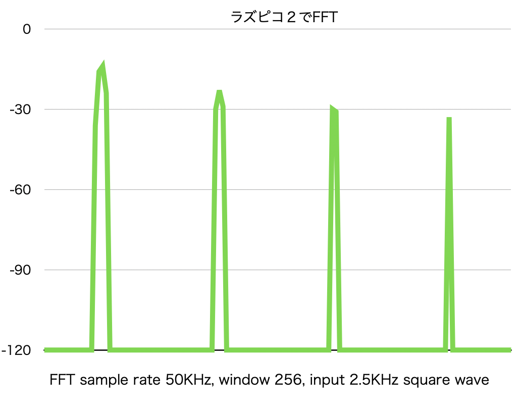
デバッガからの読み出し値をプロットしてみた、奇数の高調波がきちんと検出できている
<現状のコード:WordPressのテキスト機能で貼り付けると崩れるので本文にしてます>
ADCのサンプリングとFFTは一回だけで打ち止め、デバッグ用にですが
/* See https://m0agx.eu/practical-fft-on-microcontrollers-using-cmsis-dsp.html */
//
// DMA transfer & interrupt handling version
//
#include <math.h>
#include <stdio.h>
#include “arm_math.h”
#include “pico/stdlib.h”
#include “pico/time.h”
#include “hardware/sync.h”
// For ADC input & IRQ:
#include “hardware/adc.h”
#include “hardware/dma.h”
#include “hardware/irq.h”
// use multi core
#include “pico/multicore.h”
#include “hardware/pio.h”
#include “hardware/pwm.h”
void core1_main();
#define FFT_SIZE 256
// Channel 0 is GPIO26 for ADC sampling
#define CAPTURE_CHANNEL 0
int dma_chan;
uint32_t start_time;
uint32_t end_time;
q15_t fft_output[FFT_SIZE * 2]; // 出力(複素数 interleaved)
q15_t mag_squared[FFT_SIZE]; // パワースペクトル(Q13形式)
q15_t hann_window[FFT_SIZE];
arm_rfft_instance_q15 fft_instance;
#define RAW_SAMPLES 2560
#define DOWNSAMPLED 256
#define DECIMATE_N 10
uint16_t capture_buf[RAW_SAMPLES];
q15_t filtered_downsampled[DOWNSAMPLED];
static inline q15_t lowpass_filter_q15(q15_t input, q15_t prev, q15_t alpha)
{
int32_t one_minus_alpha = 32768 – alpha; // Q15で (1 – α)
int32_t filtered = ((int32_t)input * alpha + (int32_t)prev * one_minus_alpha) >> 15;
return (q15_t)__SSAT(filtered, 16);
}
void filter_and_downsample()
{
q15_t prev = 0; // IIRの初期値
q15_t alpha = 8192; // Q15形式の係数(約 0.25)
int down_idx = 0;
for (int i = 0; i < RAW_SAMPLES; i++)
{
// ADC raw は 12bit(0~4095)想定 → 中心化&スケーリング
int32_t centered = (int32_t)capture_buf[i] – 2048;
q15_t sample = (q15_t)__SSAT(centered << 3, 16); // ≒ Q15スケーリング Clipping would not happen in this case
// IIR フィルタ適用
prev = lowpass_filter_q15(sample, prev, alpha);
// N点ごとに出力へ保存
if ((i % DECIMATE_N) == 0 && down_idx < DOWNSAMPLED)
{
filtered_downsampled[down_idx++] = prev;
}
}
}
// FFT & Power calc
void perform_fft_and_power_spectrum(arm_rfft_instance_q15 *instance, q15_t *input, q15_t *output, q15_t *power_spectrum)
{
arm_rfft_q15(instance, input, output);
arm_cmplx_mag_squared_q15(output, power_spectrum, FFT_SIZE);
}
// ADC DMA transfer set up
void adc_dma_init()
{
// Init GPIO for analogue use: hi-Z, no pulls, disable digital input buffer.
adc_gpio_init(26 + CAPTURE_CHANNEL);
adc_init();
adc_select_input(CAPTURE_CHANNEL);
adc_fifo_setup(
true, // Write each completed conversion to the sample FIFO
true, // Enable DMA data request (DREQ)
1, // DREQ (and IRQ) asserted when at least 1 sample present
false, // We won’t see the ERR bit because of 8 bit reads; disable.
false // not Shift each sample to 8 bits when pushing to FIFO
);
adc_set_clkdiv(1.0f);
sleep_ms(1000);
// Set up the DMA to start transferring data as soon as it appears in FIFO
dma_chan = dma_claim_unused_channel(true);
dma_channel_config cfg = dma_channel_get_default_config(dma_chan);
// Reading from constant address, writing to incrementing byte addresses
channel_config_set_transfer_data_size(&cfg, DMA_SIZE_16);
channel_config_set_read_increment(&cfg, false);
channel_config_set_write_increment(&cfg, true);
// Pace transfers based on availability of ADC samples
channel_config_set_dreq(&cfg, DREQ_ADC);
dma_channel_configure(dma_chan, &cfg,
capture_buf, // dst
&adc_hw->fifo, // src
RAW_SAMPLES, // transfer count
false // start when triggered
);
dma_channel_set_irq0_enabled(dma_chan, true);
adc_run(true);
}
// to apply Hann window & call FFT/Power calc
void fft_exec()
{
// q15_t input[FFT_SIZE];
q15_t windowed_input[FFT_SIZE];
float hann_correction = 1.0f / 0.5f; // ハニング窓で約0.5倍になる補正
start_time = time_us_32();
for (int n = 0; n < FFT_SIZE; n++)
{
int32_t val = filtered_downsampled[n] * hann_window[n];
windowed_input[n] = (q15_t)(val >> 15);
}
perform_fft_and_power_spectrum(&fft_instance, windowed_input, fft_output, mag_squared);
end_time = time_us_32();
//printf(“Execution time: %.2f us per FFT\n”, (float)(end_time – start_time));
float q13_to_float = 1.0f / 8192.0f; // Q13 → float
for (uint32_t j = 0; j <= FFT_SIZE / 2; j++)
{
float mag_q13 = (float)mag_squared[j] * q13_to_float;
float mag_corr = mag_q13 * hann_correction; // Hanning補正(約2倍)
float voltage_rms = sqrtf(mag_corr);
float db = 20.0f * log10f(voltage_rms + 1e-6f);
printf(“Bin %3u: %.2f dB\n”, j, db);
}
}
// IRQ handler
void dma_handler()
{
// stop ADC sampling
adc_run(false);
// Clear the interrupt request.
dma_hw->ints0 = 1u << dma_chan;
filter_and_downsample();
// Give the channel a new wave table entry to read from, and re-trigger it
dma_channel_set_read_addr(dma_chan, &adc_hw->fifo, false);
dma_channel_set_write_addr(dma_chan, capture_buf, false);
dma_channel_set_trans_count(dma_chan, RAW_SAMPLES, false);
dma_channel_start(dma_chan);
// adc_run(true); // make it oneshot only for debug purpose
// exec FFT process in parallel with ADC DMA transfer
fft_exec();
}
#define OUTPUT_PIN 2
void setup_pwm()
{
gpio_set_function(OUTPUT_PIN, GPIO_FUNC_PWM);
uint slice_num = pwm_gpio_to_slice_num(OUTPUT_PIN);
pwm_config config = pwm_get_default_config();
pwm_config_set_clkdiv(&config, 1.0f); // PWM clock = 125 MHz / 1 = 125 MHz
// 周期 = 25,000クロック → 2.5kHz(= 125M / 50.0k)
pwm_config_set_wrap(&config, 49999);
pwm_init(slice_num, &config, true);
// デューティー比 = 50%
pwm_set_gpio_level(OUTPUT_PIN, 25000);
}
int main()
{
stdio_init_all();
sleep_ms(1000);
setup_pwm();
multicore_launch_core1(core1_main);
// initialize the ADC buffer
adc_dma_init();
// to prepare Hanning window coefficient
for (int n = 0; n < FFT_SIZE; n++)
{
float hann = 0.5f * (1.0f – cosf(2.0f * M_PI * n / (FFT_SIZE – 1)));
hann_window[n] = (q15_t)(hann * 32767.0f);
}
// initialise FFT instance
arm_status status = arm_rfft_init_q15(&fft_instance, FFT_SIZE, 0, 1);
// to register IRQ handler and enable it
irq_set_exclusive_handler(DMA_IRQ_0, dma_handler);
irq_set_enabled(DMA_IRQ_0, true);
// first ADC sampling start
adc_run(false);
dma_channel_start(dma_chan);
adc_run(true);
// wait forever
__wfi();
//__BKPT(1);
}
// —————————————————————————-
// core1 will be used for LCD display control
void core1_main()
{
}
表示部分(ミニLCD)の検討しないと、信号の前処理(最小限オペアンプでの処理)も必要ですが、
admin
現実には窓関数を使うから、窓をかけるのと計算方法(元のソースは最後の出力配列作成時のq15の扱い方が変)だったので処理方法を見直して、対数表示でも違和感ないように見直し
<コードの波形部分以外の全部>
/* See https://m0agx.eu/practical-fft-on-microcontrollers-using-cmsis-dsp.html */

#include <math.h>
#include <ltstdio.h>

#include "arm_math.h"
#include "pico/stdlib.h"
#include "pico/time.h"

unsigned char __697hz_raw[] = {// データ部分は省略};

unsigned int __697hz_raw_len = 512;

#define FFT_SIZE 256

// バッファ宣言
q15_t input_signal[FFT_SIZE];   // 入力(実数信号)
q15_t fft_output[FFT_SIZE * 2]; // 出力(複素数 interleaved)
q15_t mag_squared[FFT_SIZE];    // パワースペクトル(Q13形式)

void perform_fft_and_power_spectrum(arm_rfft_instance_q15 *instance, q15_t *input, q15_t *output, q15_t *power_spectrum)
{
    arm_rfft_q15(instance, input, output);
    arm_cmplx_mag_squared_q15(output, power_spectrum, FFT_SIZE);
}

int main()
{
    stdio_init_all();
    sleep_ms(1000);

    q15_t *input = (q15_t *)__697hz_raw;
    q15_t windowed_input[FFT_SIZE];

    float scaling_factor = 1.0f / 8192.0; // Q13 → float
    float hann_correction = 1.0f / 0.5f;  // ハニング窓で約0.5倍になる補正

    // ハニング窓
    for (int n = 0; n < FFT_SIZE; n++) { float hann = 0.5f * (1.0f - cosf(2.0f * M_PI * n / (FFT_SIZE - 1))); q15_t hann_q15 = (q15_t)(hann * 32767.0f); int32_t val = (int32_t)input[n] * hann_q15; windowed_input[n] = (q15_t)(val >> 15);
    }

    arm_rfft_instance_q15 fft_instance;
    arm_status status = arm_rfft_init_q15(&fft_instance, FFT_SIZE, 0, 1);
    printf("FFT init %d\n", status);

    uint32_t start_time = time_us_32();

    perform_fft_and_power_spectrum(&fft_instance, windowed_input, fft_output, mag_squared);

    uint32_t end_time = time_us_32();

    printf("Execution time: %.2f us per FFT\n", (float)(end_time - start_time));

    for (uint32_t j = 0; j <= FFT_SIZE / 2; j++)
    {
        float mag = mag_squared[j] * scaling_factor * hann_correction;
        float db = 10.0f * log10f(mag + 1e-12f); // 0対策のオフセット付き
        printf("Bin %3u: %.2f dB\n", j, db);
    }

    printf("\n");
    __BKPT(1);
}
<結果>
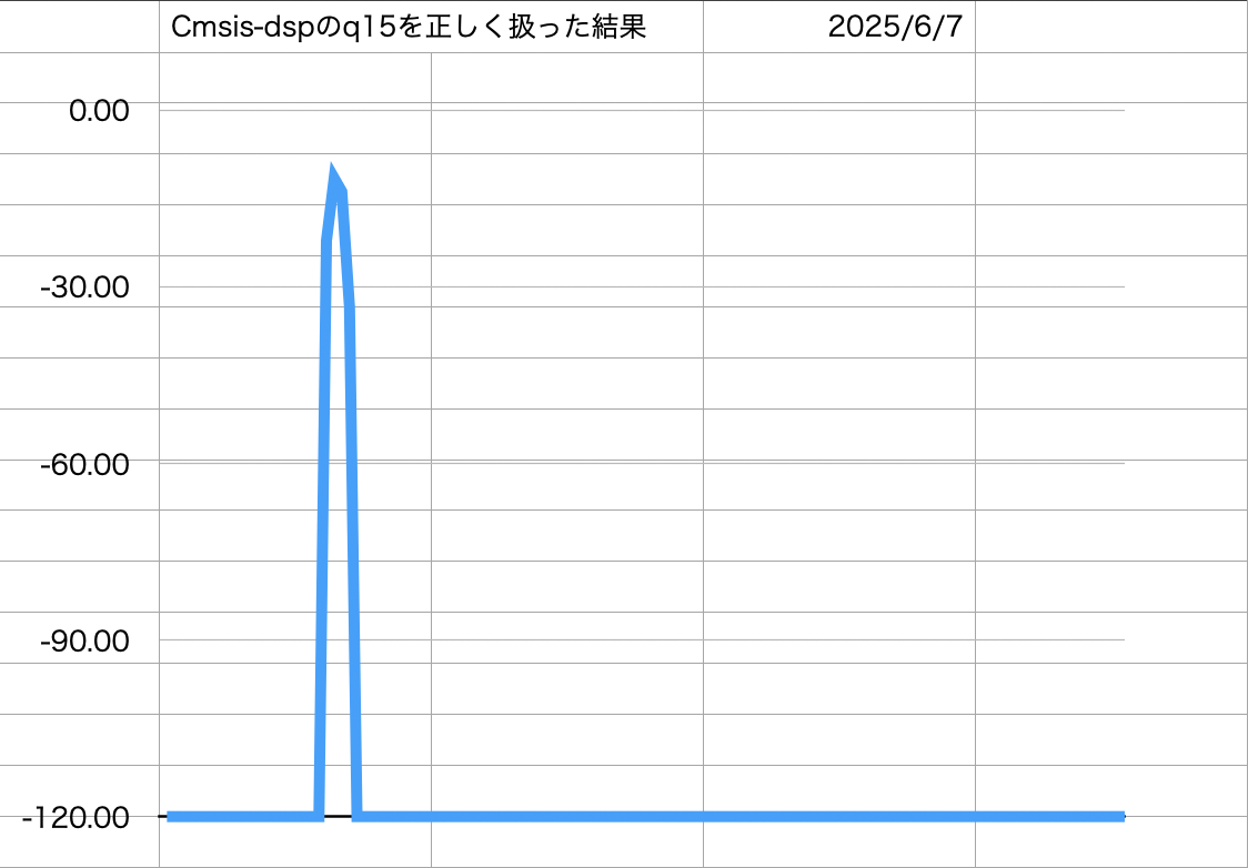
窓はHanningが適切っぽいし、フレーム数も256で簡易表示なら速度的にも速いから良さそうだ
ADCはノイジーだけど内蔵の12 bitsでやってみるのがPoCには適切だろうと思う
admin